AXI-S Slave Interface Design
AXI-S Slave Interface Design
- 7 min read
Developing a module or a design with a standard interface offers significant convenience to the RTL designer. It brings the advantages of being easy to integrate into other projects and of sharing a common structure that is compatible with designs developed by others.
AXI4-Stream (AXI-S), whose standard was defined by ARM and which is used in systems requiring high-volume, unidirectional data flow, is frequently used in video transmission standards such as HDMI and VGA.
AXI-S has a fairly simple structure. It consists of one-bit status signals through which the transmitting and receiving sides tell each other that they are ready, a one-bit signal used to synchronise the data, a multi-bit bus carrying the data itself, and a one-bit signal whose function can be defined by the user.
Taking a closer look at the AXI-S signals that are used most commonly:
- ACLK: The clock signal. All operations are performed on the rising edge of this signal.
- ARESETN: The asynchronous reset signal. It is active low. It must be released synchronously with ACLK.
- TDATA: The interface over which the data is transferred. It is an output for the master and an input for the slave. Its width can be any integer multiple of 8 bits.
- TVALID: The interface indicating that the data on TDATA is valid. It is an output for the master and an input for the slave.
- TREADY: The interface with which the slave device indicates that it can accept data. It is an input for the master and an output for the slave.
- TUSER: An interface that can be used for a function defined by the user. It is an output for the master and an input for the slave
- TLAST: The interface indicating that the last data word has been sent. It is an output for the master and an input for the slave
Apart from these interfaces, you can review the operation of the TSTRB, TKEEP, TID and TDEST signals defined in the specification here.
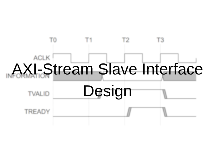
AXI-S is a protocol that starts transferring data directly, without any additional handshake or address transaction, as soon as both the TREADY and TVALID signals are ‘1’. The operating principle of the AXI-S protocol can be examined through the interface signals in Figure 1.
 Figure 1 - Operating principle of the AXI-S protocol
In addition, to prevent deadlock, the protocol rules state that the TVALID signal may not wait for the TREADY signal to become ‘1’.
In this article an AXI-S slave interface is designed that can be used directly in video transmission applications such as HDMI and VGA.
In HDMI and VGA interfaces, data synchronisation between the image produced by the source and the interface performing the transmission is critical. Synchronisation between the source and the video interface, which run in different clock domains, is provided by buffers. Provided that the conditions “amount of data produced >= amount of data transmitted” and “source clock frequency >= interface clock frequency” are met, uninterrupted data transfer can be achieved with a single FIFO performing the clock domain crossing. In this flow, which is built around a FIFO supporting two clock inputs, the clock domain crossing capability of the FIFO is used. In addition, in accordance with the AXI-S protocol, the TREADY signal is generated from the full/empty status of the FIFO. In order to keep the latency of the system to a minimum, the design does not wait for a complete line to accumulate in the FIFO before starting to read. Since the source frequency (ACLK) is higher than the target frequency (PIXEL_CLK), the FIFO is expected to feed the display module without interruption.
Xilinx and most other IP core developers use the TUSER signal as the Start of Frame (SoF) signal in video-oriented AXI-S applications. In this design too, the TUSER signal is used for the SoF function. The SoF signal is driven to ‘1’ on the first pixel of the first line of the displayed image.
In the same manner, the TLAST signal is used as the End of Line (EoL) signal. The EoL signal is driven to ‘1’ on the last pixel of the line being transferred.
The HDMI standard requires each of the RGB channels to be transferred as 8 bits. In this design the TDATA signal is a 24-bit bus formed by concatenating the Red (R), Green (G) and Blue (B) channels in that order. When this colour data is written into the FIFO it is concatenated with the TUSER (SoF) and TLAST (EoL) signals, giving a total of 26 bits. The TUSER (SoF) and TLAST (EoL) bits are placed at bit 25 and bit 24 respectively. This allows the destination module that reads the data out of the FIFO to handle its own synchronisation.
The FIFO is configured as First Word Fall Through (FWFT), which always keeps the data ready at the output. As a result, the data flow can start immediately once TREADY and TVALID are ‘1’, as the AXI-S protocol requires, with no clock cycle of latency. Using the status signals of the FIFO, TREADY is driven to ‘1’ while the FIFO is not full to indicate that incoming data can be accepted, and likewise the data is written into the FIFO whenever valid data arrives (TVALID = ‘1’) while the FIFO is not full.
The SoF signal is driven out of the module concurrently from the already available FIFO data output. The reason for this is that the module generating the video synchronisation signals has to detect the start of a new frame immediately, without waiting for the data to be written into a register.
Finally, while the module is enabled by the enable input coming from the module that generates the HDMI or VGA synchronisation signals, the data leaving the FIFO is driven out through a register clocked at the operating frequency of the interface module.
The configuration settings of the FWFT FIFO, created with Vivado 2024.1 using FIFO Generator 13.2 (Rev. 10), are given in Figure 2.
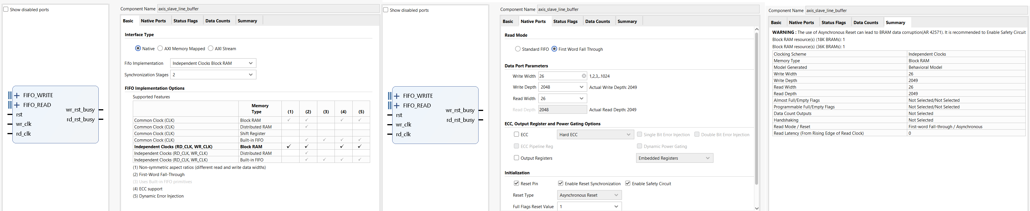 Figure 2 - FWFT FIFO configuration settings
The AXI-S slave interface code, written in VHDL and used in a custom-designed HDMI IP core, is given below.
library ieee;
use ieee.std_logic_1164.all;
use IEEE.numeric_std.all;

entity axis_slave_interface is

	port
	(
		--CLK/Reset interface
		PIXEL_CLK_i		: in  std_logic;   -- pixel clock
		PIXEL_RESET_i	: in  std_logic;   -- PIXEL_CLK domain reset

		--HDMI Interface
		DATA_o			: out std_logic_vector(23 downto 0);
		DISPLAY_EN_i	: in  std_logic;
		SOF_o			: out std_logic;
		EOL_o			: out std_logic;

		--AXI4-Stream CLK/Reset interface
		ACLK			: in  std_logic;
		ARESETn			: in  std_logic;

		--AXI4-Stream slave (stream domain)
		S_AXIS_TDATA	: in  std_logic_vector(23 downto 0);
		S_AXIS_TVALID	: in  std_logic;
		S_AXIS_TREADY	: out std_logic;
		S_AXIS_TUSER	: in  std_logic;   -- Start of Frame (first pixel of frame)
		S_AXIS_TLAST 	: in  std_logic    -- End of Line
	);
end entity;

architecture axis_slave_interface_beh of axis_slave_interface is

	component axis_slave_line_buffer
		port
		(
			rst 	: in std_logic;
			wr_clk 	: in std_logic;
			rd_clk 	: in std_logic;
			din 	: in std_logic_vector(25 downto 0);
			wr_en 	: in std_logic;
			rd_en 	: in std_logic;
			dout 	: out std_logic_vector(25 downto 0);
			full 	: out std_logic;
			empty 	: out std_logic
		);
	end component;

	constant DW	: integer := 26;  -- [25]=SOF, [24]=EOL, [23:0]=RGB888

	-- FIFO signals
	signal wr_en		: std_logic;
	signal rd_en		: std_logic;
	signal fifo_full	: std_logic;
	signal fifo_empty	: std_logic;
	signal din			: std_logic_vector(DW-1 downto 0);
	signal dout			: std_logic_vector(DW-1 downto 0);

begin

	----------------------------------------------------------------------------
	-- Write side (ACLK / stream domain)
	----------------------------------------------------------------------------
	din           <= S_AXIS_TUSER & S_AXIS_TLAST & S_AXIS_TDATA;
	wr_en         <= S_AXIS_TVALID and (not fifo_full);
	S_AXIS_TREADY <= (not fifo_full);

	----------------------------------------------------------------------------
	-- Read side (PIXEL_CLK / video domain) - FWFT
	----------------------------------------------------------------------------
	rd_en <= DISPLAY_EN_i and (not fifo_empty);

	SOF_o <= dout(25) and (not fifo_empty);

	READ_OUT:
	process(PIXEL_CLK_i)
	begin
		if rising_edge(PIXEL_CLK_i) then
			if PIXEL_RESET_i = '1' then
				DATA_o <= (others=>'0');
				EOL_o  <= '0';
			else
				if DISPLAY_EN_i = '1' then
					if fifo_empty = '0' then
						DATA_o <= dout(23 downto 0);
						EOL_o  <= dout(24);
					else
						-- Underflow -> black, for protecting timing
						DATA_o <= (others=>'0');
						EOL_o  <= '0';
					end if;
				else
					EOL_o <= '0';
				end if;
			end if;
		end if;
	end process;

	----------------------------------------------------------------------------
	-- Async FIFO (CDC + buffering)
	----------------------------------------------------------------------------

	CDC_FIFO : axis_slave_line_buffer
	port map
	(
		rst     => not ARESETn,
		wr_clk 	=> ACLK,
		rd_clk 	=> PIXEL_CLK_i,
		din 	=> din,
		wr_en 	=> wr_en,
		rd_en 	=> rd_en,
		dout 	=> dout,
		full 	=> fifo_full,
		empty 	=> fifo_empty
	);

end architecture;