PWM Signal Generation with VHDL and Verilog
PWM Signal Generation with VHDL and Verilog
- 10 min read
PWM Signal Generation with VHDL and Verilog
PWM (Pulse Width Modulation) is an output format widely used in electronic applications, in which the value of the output is controlled by varying the amount of time the digital output stays active. With this output format, the effect of an analogue output can be produced using only a digital signal. It is also possible to transfer data between digital systems by making use of the timing parameters of the PWM signal.
PWM is based on the principle of switching digital systems rapidly. It works by changing the power delivered to the output through the on time (Ton) and off time (Toff) within a period. The structure of the PWM signal is given in Figure 1.
T: Period Ton: The time the output is held active at ‘1’ Duty: Expressed as the Ton/T ratio.
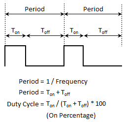
Figure 1 - Structure of the PWM signal
In the PWM signal structure shown in Figure 1, the power delivered to the output over one period is equal to Pmax*(Ton/T). Mathematically this can be written as follows.

Since the term on the right that is multiplied by 0 vanishes, the equation simplifies to the following form.

The PWM signal format is based on changing the power delivered to the output by varying the Ton/T ratio within a period. For example, a system that is to be driven at 100% power requires a Ton/T ratio of 1, whereas a system that is to run at 10% power requires a Ton/T ratio of 0.1.
By changing the duty ratio it becomes possible to change output quantities such as the power, the voltage or the position of the system being controlled. Varying the duty value changes the average time the output stays active and therefore lets the effective output value be adjusted. This method is particularly suitable for systems that can be switched on and off rapidly (heaters, lighting products, motors, SMPS units and so on), whose output power or speed can be controlled in this way. Because the switching is done very fast, at a frequency higher than the perception frequency of a human being or of the measuring system, the output behaves as though it were being controlled by a true analogue signal.
A PWM implementation in the VHDL and Verilog hardware design languages is given below. In these designs the clock frequency, the frequency of the PWM signal and the resolution of the PWM input value that controls the module are all defined as generics. The input and output parameters can therefore be adjusted as required.
The number of clock cycles required for one unit of resolution is calculated from the generic parameters at synthesis time and stored in the constant named pwm_tick_counter_limit_c. The input named PWM_i is sampled at the start of every PWM period and written into a signal named pwm_value. When pwm_tick_counter reaches pwm_tick_counter_limit_c-1, that is, when the time required for one unit of resolution has elapsed, the signal named pwm_tick is driven to ‘1’ for one clock cycle. When pwm_tick is ‘1’, the value of the signal named pwm_duty_counter, which holds the position within the PWM period in units of resolution, is incremented by one. Comparing the value taken from the PWM_i input with pwm_duty_counter determines whether the PWM signal should be in its Ton or Toff state. While the counter value lies between 0 and pwm_value-1 the output is driven to ‘1’, producing the Ton state; when it exceeds that value the output is driven to ‘0’.
The PWM generator code written in VHDL is given below.
--VHDLVerilog.com (VerilogVHDL.com) - 2025
--PWM controller

library ieee;
use ieee.std_logic_1164.all;
use IEEE.numeric_std.all;

entity pwm_generator is
	generic
	(
		CLK_FREQ_c		: integer := 100_000_000;--CLK frequency (Hz)
		PWM_FREQ_c		: integer := 100;--PWM frequency (Hz)
		PWM_RESOLUTION_c: integer := 10--PWM resolution in bits
	);
	port
	(
		CLK_i			: in std_logic;--CLK input
		RESET_n_i		: in std_logic;--active low reset

		EN_i			: in std_logic;
		PWM_VALUE_i		: in std_logic_vector(PWM_RESOLUTION_c-1 downto 0);

		PWM_o			: out std_logic
	);
end entity;

architecture pwm_generator_beh of pwm_generator is

	--Logarithm function used to calculate the bit width of the pwm_tick_counter signal
	--Taken from the Xilinx Language Templates.
	function clogb2( depth : natural) return integer is
		variable temp    : integer := depth;
		variable ret_val : integer := 0;
	begin
		while temp > 0 loop
			ret_val := ret_val + 1;
			temp    := temp / 2;
		end loop;

		return ret_val;
	end function;

	--Constant holding the number of clock ticks required for one duty unit
	constant pwm_tick_counter_limit_c : integer := (CLK_FREQ_c + ((PWM_FREQ_c * (2**PWM_RESOLUTION_c))/2) ) / (PWM_FREQ_c * (2**PWM_RESOLUTION_c));
	signal pwm_tick_counter 		  : unsigned(clogb2(pwm_tick_counter_limit_c)-1 downto 0) := (others=>'0');--signal declaration for the time counter
	signal pwm_tick 				  : std_logic := '0';--declaration of the signal triggered when one duty unit has elapsed
	signal pwm_duty_counter 		  : unsigned(PWM_RESOLUTION_c-1 downto 0) := (others=>'0');--signal declaration for the duty counter
	signal pwm_value 			  	  : unsigned(PWM_RESOLUTION_c-1 downto 0) := (others=>'0');--signal in which the PWM input is sampled and stored at the start of the period

begin

	process(CLK_i)
	begin

		if rising_edge(CLK_i) then

			if RESET_n_i = '0' then--sync reset

				--Output clearing
				PWM_o <= '0';

				--signal clearing in the reset state
				pwm_value		 <= (others=>'0');--clear the register holding the PWM value
				pwm_tick_counter <= (others=>'0');--clear the time counter
				pwm_tick		 <= '0';--clear the signal that triggers the period counter
				pwm_duty_counter <= (others=>'0');--clear the period counter.

			else

				if EN_i = '1'  then--if the ENABLE input is active

					if pwm_duty_counter = 0 then--if the period is complete, accept a new input value
						pwm_value <= unsigned(PWM_VALUE_i);--sample the PWM input
					end if;

					--counter used to measure the unit duty period
					if pwm_tick_counter = to_unsigned(pwm_tick_counter_limit_c-1,clogb2(pwm_tick_counter_limit_c)) then--if the end of the unit duty period has been reached
						pwm_tick_counter <= (others=>'0');--clear the unit duty counter
						pwm_tick <= '1';
					else
						pwm_tick_counter <= pwm_tick_counter + 1;--increment the unit duty counter.
						pwm_tick <= '0';
					end if;

					--counter used to measure the PWM period
					if pwm_tick = '1' then--if the end of the PWM period has been reached
						if pwm_duty_counter = (pwm_duty_counter'range => '1') then--if the end of the PWM period has been reached (all bits are 1)
							pwm_duty_counter <= (others=>'0');--clear the duty counter
						else
							pwm_duty_counter <= pwm_duty_counter + 1;--increment the duty counter.
						end if;
					end if;

					if pwm_duty_counter < pwm_value then--if the PWM is in its Ton phase
						PWM_o <= '1';
					else--if the PWM is in its Toff phase
						PWM_o <= '0';
					end if;

				else--if the ENABLE input is inactive

					--Output clearing
					PWM_o <= '0';

					pwm_value		 <= (others=>'0');--clear the register holding the PWM value
					pwm_tick_counter <= (others=>'0');--clear the time counter
					pwm_tick		 <= '0';--clear the signal that triggers the period counter
					pwm_duty_counter <= (others=>'0');--clear the period counter.

				end if;

			end if;--RESET_n_i

		end if;--rising_edge

	end process;

end architecture;
The PWM generator code written in Verilog, which is exactly equivalent to the code above, is given below.
//VHDLVerilog.com (VerilogVHDL.com) - 2025
//PWM controller

module pwm_generator
#(
	parameter CLK_FREQ_c		= 100_000_000,//CLK frequency (Hz)
	parameter PWM_FREQ_c		= 100,//PWM frequency (Hz)
	parameter PWM_RESOLUTION_c	= 10//PWM resolution in bits
)
(
	input CLK_i,//CLK input
	input RESET_n_i,//active low reset

	input EN_i,
	input [PWM_RESOLUTION_c-1:0] PWM_VALUE_i,

	output reg PWM_o
);


    //Logarithm function used to calculate the bit width of the pwm_tick_counter signal
    //Taken from the Xilinx Language Templates (***).
    function integer clogb2;
    input integer depth;
      for (clogb2=0; depth>0; clogb2=clogb2+1)
        depth = depth >> 1;
    endfunction

	//Constant holding the number of clock ticks required for one duty unit
	localparam pwm_tick_counter_limit_c = (CLK_FREQ_c + ((PWM_FREQ_c * (2**PWM_RESOLUTION_c))/2) ) / (PWM_FREQ_c * (2**PWM_RESOLUTION_c));
	reg [clogb2(pwm_tick_counter_limit_c)-1:0] pwm_tick_counter = {clogb2(pwm_tick_counter_limit_c){1'b0}};//signal declaration for the time counter
	reg pwm_tick = 1'b0;//declaration of the signal triggered when one duty unit has elapsed
	reg [PWM_RESOLUTION_c-1:0] pwm_duty_counter = 0;//signal declaration for the duty counter
	reg [PWM_RESOLUTION_c-1:0] pwm_value = 0;//signal in which the PWM input is sampled and stored at the start of the period

	always@(posedge CLK_i)
	begin
		if(~RESET_n_i) begin //sync reset

				//Output clearing
				PWM_o <= 1'b0;

				//signal clearing in the reset state
				pwm_value		 <= 0;//clear the register holding the PWM value
				pwm_tick_counter <= 0;//clear the time counter
				pwm_tick		 <= 1'b0;//clear the signal that triggers the period counter
				pwm_duty_counter <= 0;//clear the period counter.

		end else begin

			if(EN_i) begin//if the ENABLE input is active

				if(pwm_duty_counter == 0)//if the period is complete, accept a new input value
					pwm_value <= PWM_VALUE_i;//sample the PWM input

				//counter used to measure the unit duty period
                    if(pwm_tick_counter == (pwm_tick_counter_limit_c-1)) begin//if the end of the unit duty period has been reached
                        pwm_tick_counter <= 0;//clear the unit duty counter
                        pwm_tick <= 1'b1;
                    end else begin
                        pwm_tick_counter <= pwm_tick_counter + 1;//increment the unit duty counter.
                        pwm_tick <= 1'b0;
                    end

				//counter used to measure the PWM period
				if(pwm_tick == 1)//if the end of the PWM period has been reached
					if(pwm_duty_counter == {PWM_RESOLUTION_c{1'b1}}) //if the end of the PWM period has been reached (all bits being 1)
						pwm_duty_counter <= 0;//clear the duty counter
					else
						pwm_duty_counter <= pwm_duty_counter + 1;//increment the duty counter.

				if(pwm_duty_counter < pwm_value)//if the PWM is in its Ton phase
					PWM_o <= 1'b1;
				else//if the PWM is in its Toff phase
					PWM_o <= 1'b0;

			end else begin//if the ENABLE input is inactive

				//Output clearing
                PWM_o <= 1'b0;

                //signal clearing in the reset state
                pwm_value         <= 0;//clear the register holding the PWM value
                pwm_tick_counter <= 0;//clear the time counter
                pwm_tick         <= 1'b0;//clear the signal that triggers the period counter
                pwm_duty_counter <= 0;//clear the period counter.

			end

		end
	end

endmodule
The testbench code written in VHDL is given below.
--VHDLVerilog.com (VerilogVHDL.com) - 2025
--PWM controller testbench
library IEEE;
use IEEE.STD_LOGIC_1164.ALL;

entity pwm_generator_tb is

	generic
	(
		CLK_FREQ_c		: integer := 100_000_000;--CLK frequency (Hz)
		PWM_FREQ_c		: integer := 100;--PWM frequency (Hz)
		PWM_RESOLUTION_c: integer := 10--PWM resolution in bits
	);

end entity;

architecture DUT of pwm_generator_tb is

---------------------------------------------------------------------------------------------------
--components
---------------------------------------------------------------------------------------------------
	component pwm_generator is
		generic
		(
			CLK_FREQ_c		: integer := 100_000_000;--CLK frequency (Hz)
			PWM_FREQ_c		: integer := 100;--PWM frequency (Hz)
			PWM_RESOLUTION_c: integer := 10--PWM resolution in bits
		);
		port
		(
			CLK_i			: in std_logic;--CLK input
			RESET_n_i		: in std_logic;--active low reset

			EN_i			: in std_logic;
			PWM_VALUE_i		: in std_logic_vector(PWM_RESOLUTION_c-1 downto 0);

			PWM_o			: out std_logic
		);
	end component;

---------------------------------------------------------------------------------------------------
--signals
---------------------------------------------------------------------------------------------------
	constant clock_period_c	: time := 10ns;--100MHz

	signal clk				: std_logic := '0';--clk
	signal reset_n			: std_logic := '1';--active low reset
	signal en				: std_logic := '0';--enable

	signal pwm_value		: std_logic_vector(PWM_RESOLUTION_c-1 downto 0) := (others=>'0');

begin

	--clock generator
	clock_process :
	process
	begin
		clk <= '1';
		wait for clock_period_c/2;
		clk <= '0';
		wait for clock_period_c/2;
	end process;

	PWM_GENERATOR_TEST :
	process
	begin

		reset_n <= '0';--reset asserted
		en <= '0';
		wait for clock_period_c;
		reset_n <= '1';--reset released
		pwm_value <= "0000000000";--0
		wait for 1ms;
		en <= '1';
		wait for 15ms;
		pwm_value <= "0010000000";
		wait for 20ms;
		pwm_value <= "0001000000";
		wait for 20ms;
		pwm_value <= "1000000000";
		wait for 3.5ms;
		pwm_value <= "1111111111";
		en <= '0';
		wait for 15ms;
		pwm_value <= "1111111111";
		en <= '1';
		wait for 15ms;
		en <= '0';
		pwm_value <= "0000000000";

		wait;

	end process;

---------------------------------------------------------------------------------------------------
--instantiations
---------------------------------------------------------------------------------------------------
	DUT : pwm_generator
	generic map
	(
		CLK_FREQ_c		=> CLK_FREQ_c,
		PWM_FREQ_c		=> PWM_FREQ_c,
		PWM_RESOLUTION_c=> PWM_RESOLUTION_c
	)
	port map
	(
		CLK_i			=> clk,
		RESET_n_i		=> reset_n,

		EN_i			=> en,
		PWM_VALUE_i		=> pwm_value,

		PWM_o			=> open
	);

end architecture;
The testbench code written in Verilog, which is exactly equivalent to the testbench above, is given below.
//VHDLVerilog.com (VerilogVHDL.com) - 2025
//PWM controller testbench
`timescale 1ns / 1ns
module pwm_generator_tb
	#
	(
		parameter CLK_FREQ_c = 100_000_000,//CLK frequency (Hz)
		parameter PWM_FREQ_c = 100,//PWM frequency (Hz)
		parameter PWM_RESOLUTION_c = 10//PWM resolution in bits
	);

	localparam clock_period_c = 10;

	reg clk		= 1'b0;//clk
	reg reset_n	= 1'b0;//active low reset
	reg en		= 1'b0;//enable

	reg [PWM_RESOLUTION_c-1:0] pwm_value = 0;

	always #(clock_period_c/2) clk=~clk; //100MHz

	initial begin
		reset_n <= 1'b0;//reset asserted
		en <= 1'b0;
		#clock_period_c
		reset_n <= 1'b1;//reset released
		pwm_value <= 10'b0000000000;//0
		#1000000//1ms
		en <= 1;
		#15000000//15ms
		pwm_value <= 10'b0010000000;
		#20000000//20ms
		pwm_value <= 10'b0001000000;
		#20000000//20ms
		pwm_value <= 10'b1000000000;
		#20000000//20ms
		pwm_value <= 10'b1111111111;
		en <= 0;
		#3500000//3.5ms
		pwm_value <= 10'b1111111111;
		en <= 1;
		#15000000//15ms
		en <= 0;
		pwm_value <= 10'b0000000000;

		$stop;

		end

	pwm_generator
	#(
		.CLK_FREQ_c		  (CLK_FREQ_c),
		.PWM_FREQ_c		  (PWM_FREQ_c),
		.PWM_RESOLUTION_c (PWM_RESOLUTION_c)
	)
	DUT
	(
		.CLK_i		 (clk),
		.RESET_n_i	 (reset_n),

		.EN_i		 (en),
		.PWM_VALUE_i (pwm_value),

		.PWM_o		 ()
	);

endmodule
The waveform output of the testbench codes above is given in Figure 2.
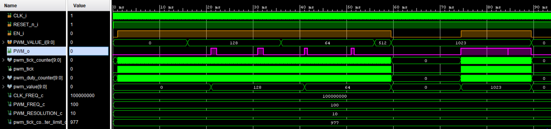
Figure 2 - Waveform output
Figure 1 used in this article is taken from Learn Electronics India.