Moving Average Filter with VHDL
Moving Average Filter with VHDL
- 15 min read
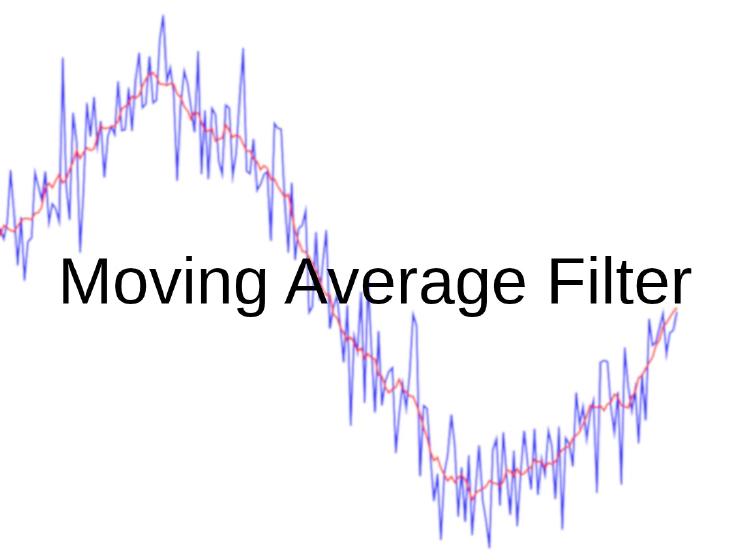
Moving Average Filter
A moving average filter is a filter that takes the average of successive input samples and outputs the result. It produces a stable output in response to abruptly and randomly changing inputs. Mathematically it is a convolution with a fixed-width Finite Impulse Response (FIR) function. It has a low-pass characteristic. Although it performs well in the time domain, it does not give good results in the frequency domain.
In electronics it is frequently used with analogue-to-digital converters (ADCs) and for filtering noisy input signals. In finance it is used to make sense of the value of assets. It is a highly effective structure that is easy to understand and straightforward to implement algorithmically.
Its most important parameter is the window length. The window length is the parameter that determines how many inputs are averaged. Its mathematical expression is given in Figure 1.
 Figure 1 - Mathematical expression of the moving average filter
The algorithm can be understood more clearly by examining the inputs covered by the sliding window and the outputs it produces in the animated figure given in Figure 2.
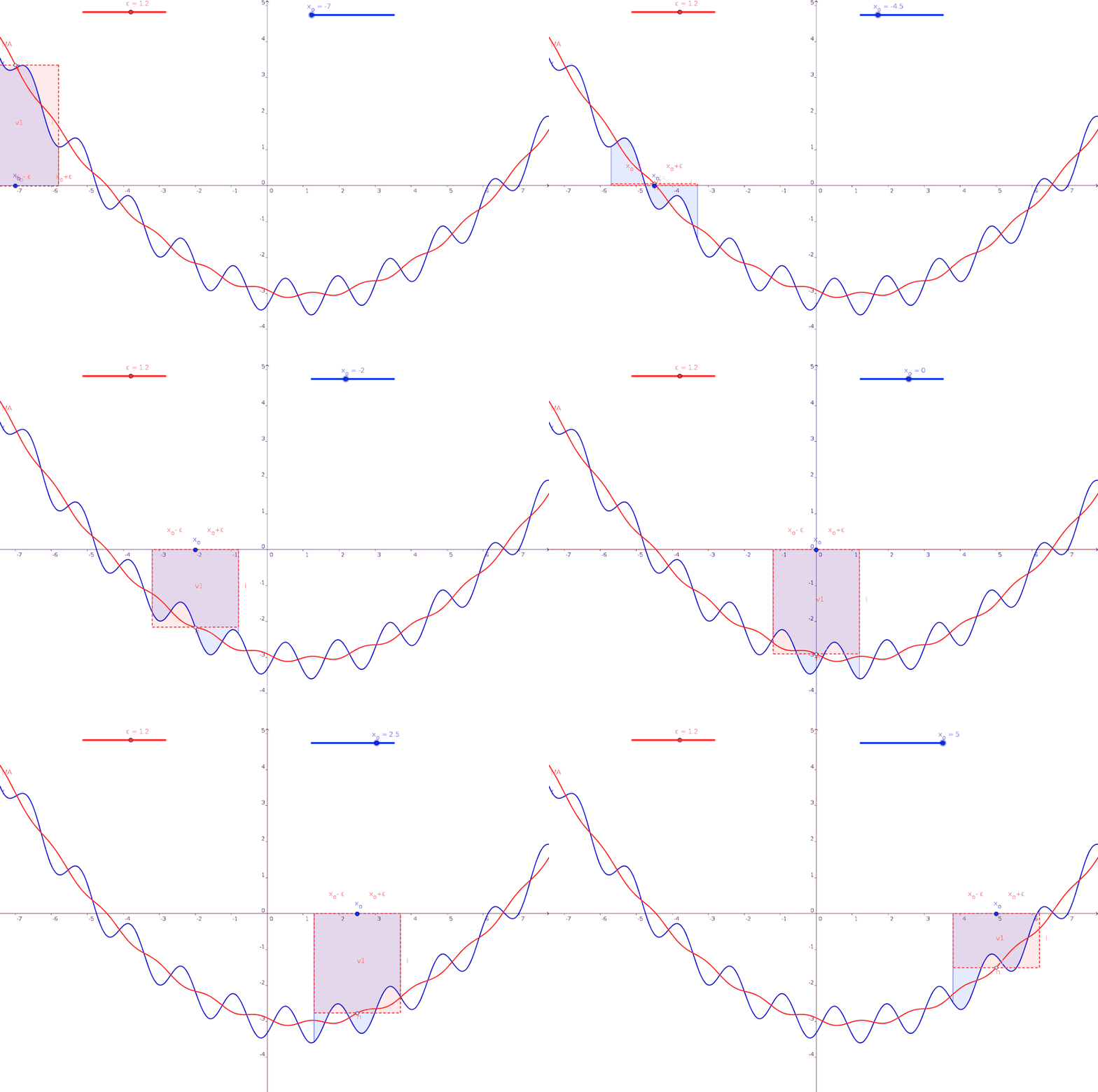 Figure 2 - Operation of the sliding window of the moving average filter
Examining the output indices shown in red and the input indices shown in blue in the operation above, it becomes clear that the window has to be completely filled with inputs before a meaningful average can be taken. The outputs produced from the index of the middle element of the fully filled window onwards are meaningful and correct. At the beginning and at the end of the signal applied to the filter, the number of samples included in the average is smaller than the window length, so the outputs produced there can be misleading.
The performance the filter shows against noisy inputs is particularly good. Examining Figure 3, the performance of filters with window lengths of 11 and 51 samples applied to the raw data on the left can be seen.
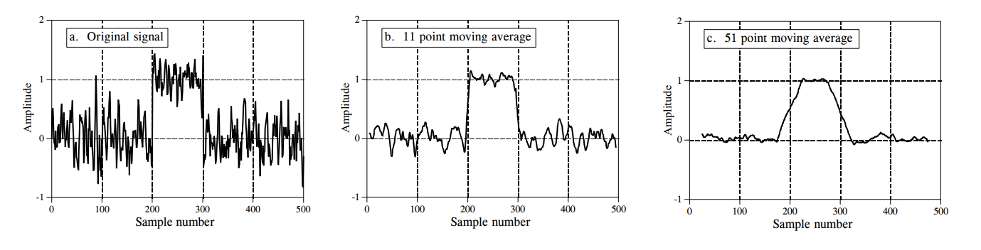 Figure 3 - Example outputs of the moving average filter for various window lengths
For a moving average filter that will run on a device such as a microcontroller or an FPGA, the continuous moving average filter algorithm, which produces identical output results, is used. This algorithm performs one addition and subtraction stage and a single division, which keeps both the software and the hardware simple. The algorithm in question is given in Figure 4.
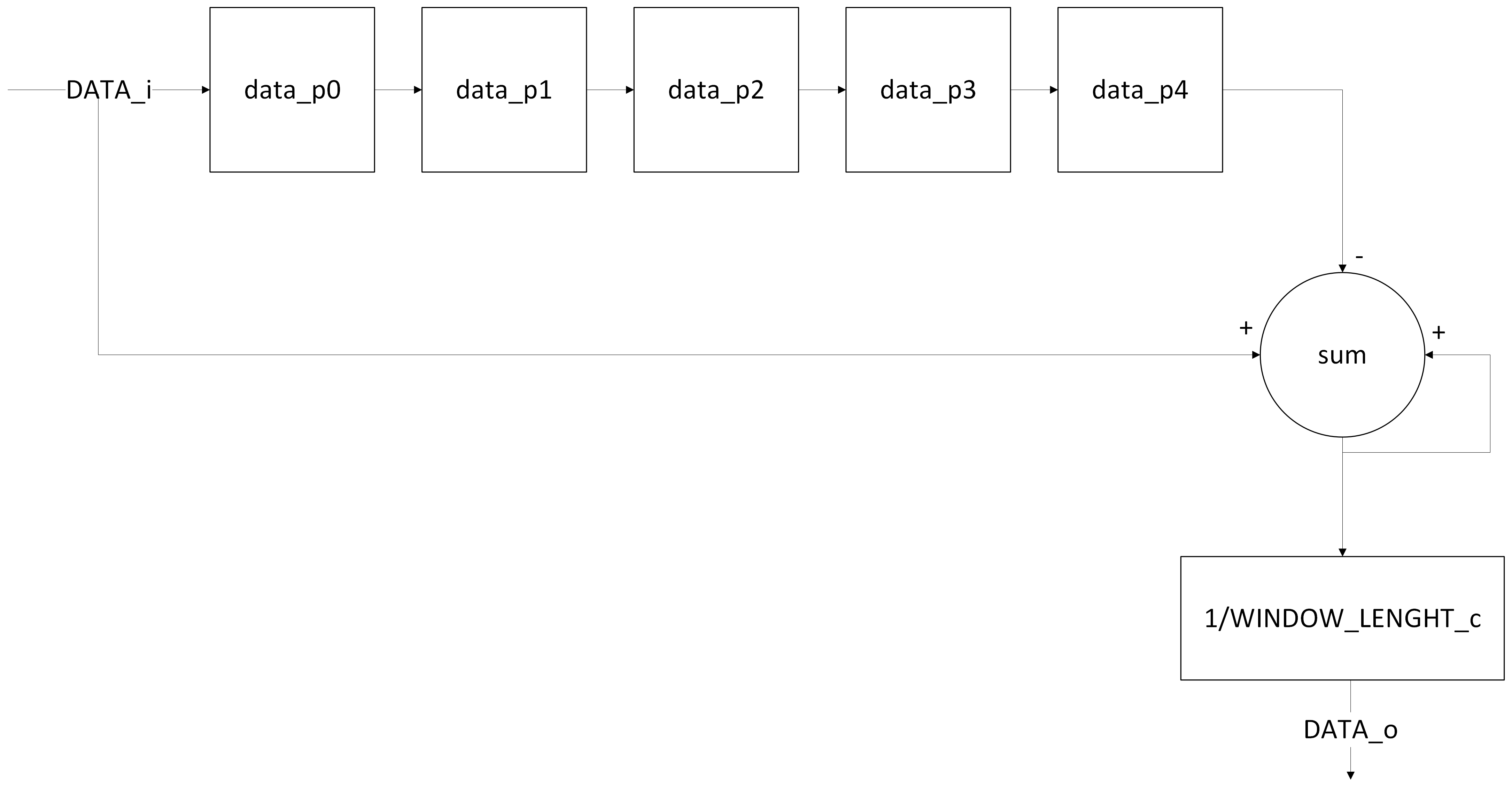 Figure 4 - The implemented algorithm
The input data is fed into a pipeline structure with as many stages as the window length. While successive inputs are continuously added into a signal named sum, the last element of the pipeline is continuously subtracted from that same sum. This structure yields the sum of exactly as many samples as the window length. Even when the input arrives continuously, the addition and subtraction operations mean that only the sum of the most recent window-length samples is retained. Once the sum of the samples over the window length has been obtained, it is divided by the window length parameter to produce the average value.
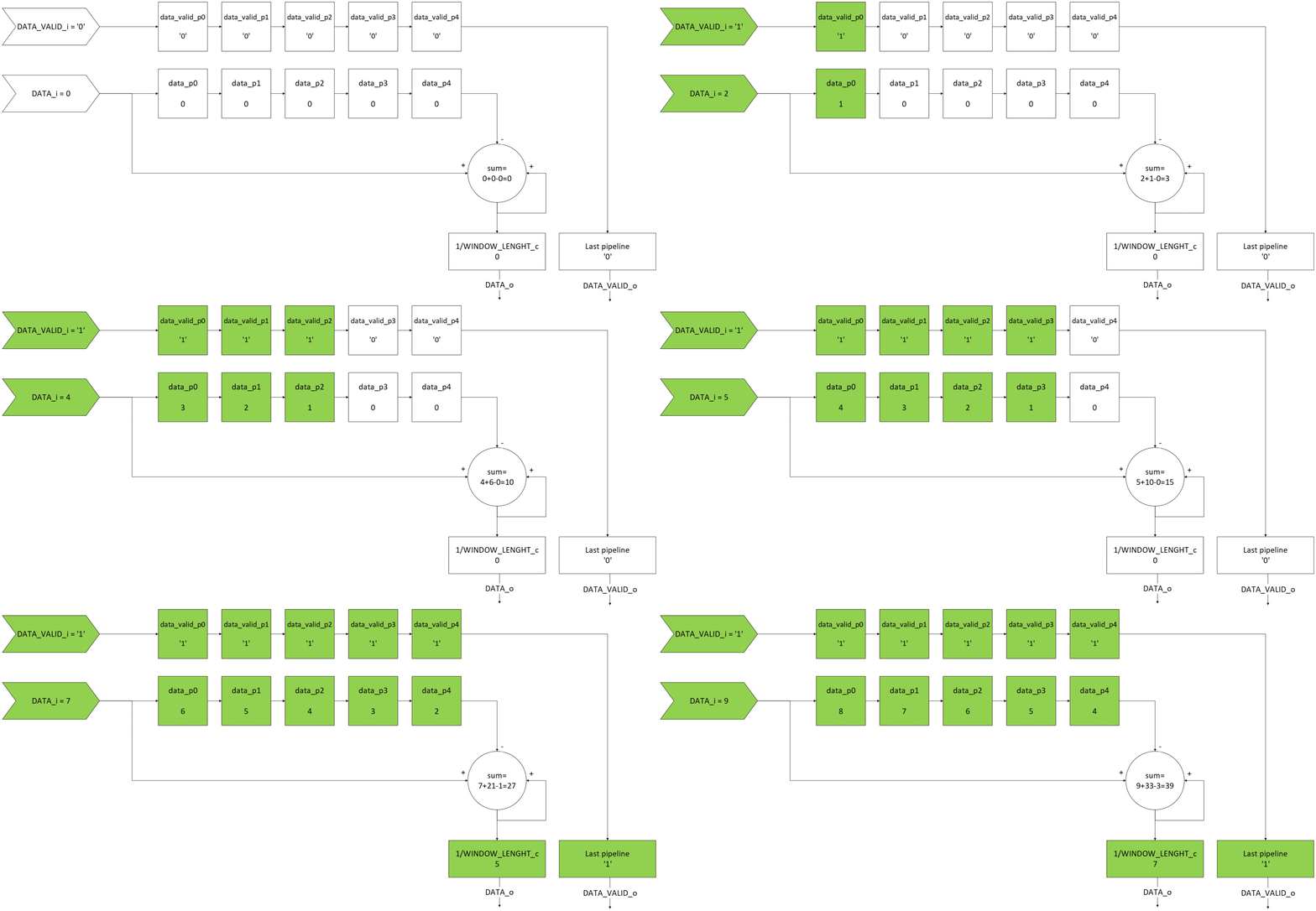 Figure 5 - Operation of the implemented algorithm
Figure 5 shows the operation of the algorithm with a window length of 5, for the input data values 1, 2, 3, 4, 5, 6, 7, 8 and 9 respectively.
Thanks to this structure, the moving average filter can be implemented with just one addition-subtraction operation and one division, independently of the window length.
Moving average filter implementation in VHDL:
The VHDL implementation of the moving average filter whose algorithm is described above is given below.
--VHDLVerilog.com (VerilogVHDL.com) - 2025
--Moving average filter
--The structure below starts producing an output after it has received WINDOW_LENGTH_c input samples.
--As long as the input signal is valid, it updates the output by taking an equally weighted average.
--While the input signal is invalid it waits, updating neither the data in the averaging window nor the output.
--When new data arrives after such a wait, averaging resumes using the samples already in the queue (the pipeline) together with the incoming data.
--The window values held in memory can be cleared with the active low synchronous reset.
--When the ROUND_TYPE_c generic is set to "FLOOR", the rounding applied while averaging goes to the next lower integer;
--when the ROUND_TYPE_c generic is set to "CEIL", the rounding applied while averaging goes to the next higher integer.
--The input must be an unsigned std_logic_vector whose length is set by the BITDEPTH_c generic.
--The output is an unsigned std_logic_vector whose length is set by the BITDEPTH_c generic.

library ieee;
use ieee.std_logic_1164.all;
use IEEE.numeric_std.all;

entity moving_average_filter is
	generic
	(
		BITDEPTH_c		: integer;--bit depth of the input and the output
		WINDOW_LENGTH_c	: integer;--size of the averaging window (a power of two is strongly recommended)
		ROUND_TYPE_c	: string--must be set to "FLOOR" or "CEIL". No other value should be selected.
	);
	port
	(
		CLK_i			: in std_logic;
		RESET_n_i		: in std_logic;--active low reset

		DATA_i			: in std_logic_vector(BITDEPTH_c-1 downto 0);
		DATA_VALID_i	: in std_logic;

		DATA_o			: out std_logic_vector(BITDEPTH_c-1 downto 0);
		DATA_VALID_o	: out std_logic
	);
end entity;

architecture moving_average_filter_beh of moving_average_filter is

	--When the inputs are summed into a signal, the width of that signal grows by ceil(log2(WINDOW_LENGTH_c)).
	--This function computes that log2 value, rounding up when the result is fractional
	function ceil_log2( depth : natural) return integer is
		variable temp	 : integer := 1;
		variable ret_val : integer := 0;
		begin
			if depth <= 1 then--if depth is less than or equal to 1, the bit depth of the window does not need to grow.
				return 0;
			else--if depth is greater than 1
				while temp < depth loop--until the value representable by the bit depth exceeds the input value
					ret_val := ret_val + 1;--increment the value to be returned after each multiplication
					temp	:= temp * 2;--starting from 1, increase the bit depth value by multiplying by 2 each time.
				end loop;
				return ret_val;
			end if;
	end function;

	type data_pipeline_type is array (0 to WINDOW_LENGTH_c-1) of std_logic_vector(BITDEPTH_c-1 downto 0);--pipeline type for the incoming data
	signal data_p : data_pipeline_type := (others=>(others=>'0'));--pipeline of the incoming data

	signal data_valid_p : std_logic_vector(WINDOW_LENGTH_c-1 downto 0) := (others=>'0');--pipeline holding whether the incoming data is valid
	signal en : std_logic := '0';--signal holding whether the output calculation is to be performed

	--signal in which the incoming samples are accumulated
	--The width required grows with every addition (in the worst case, where the largest possible input arrives every time).
	--For example, let the window length be 3 and the bit depth 8. The sum of three 8-bit samples is at most 255*3=765, and 765 is represented with 10 bits.
	--expressed mathematically, this is BITDEPTH_c + ceil_log2(WINDOW_LENGTH_c).
	signal sum : integer range 0 to ((2**(BITDEPTH_c+ceil_log2(WINDOW_LENGTH_c)))-1) := 0;

begin

	process(CLK_i)
	begin

		if rising_edge(CLK_i) then

			if RESET_n_i = '0' then--sync reset

				--signal clearing
				data_p 		<= (others=>(others=>'0'));
				data_valid_p<= (others=>'0');
				sum 		<= 0;

				--output clearing
				DATA_o		<= (others=>'0');
				DATA_VALID_o<= '0';

			else

				--pipeline 0
				if DATA_VALID_i = '1' then--if the input is valid
					data_p(0)		<= DATA_i;--pushed into the pipeline queue.
					data_valid_p(0)	<= '1';--the valid signal is set to '1' so that the window fills up.
					sum				<= sum + to_integer(unsigned(DATA_i)) - to_integer(unsigned(data_p(WINDOW_LENGTH_c-1)));

					--pipeline loop
					--generically, depending on WINDOW_LENGTH_c, it passes each pipeline element on to the next one
					for pipeline_index in 1 to WINDOW_LENGTH_c-1 loop
						data_p(pipeline_index) <= data_p(pipeline_index-1);
						data_valid_p(pipeline_index) <= data_valid_p(pipeline_index-1);
					end loop;

					en <= '1';--perform the output calculation. This signal registers DATA_VALID_i, so after DATA_VALID_i is removed
					--the samples inside the window keep being flushed for one more clock cycle.
				else
					en <= '0';--do not perform the output calculation
				end if;

				--last pipeline
				--if every pipeline stage is filled with data (no output is produced while fewer than WINDOW_LENGTH_c samples have arrived) and the output calculation is enabled
				if data_valid_p(WINDOW_LENGTH_c-1) = '1' and en = '1' then
				--since it is a generic parameter, the synthesis tool selects one of the branches below and drives it out.
					if ROUND_TYPE_c = "CEIL" then
						DATA_o		 <= std_logic_vector(to_unsigned(((sum+(WINDOW_LENGTH_c-1))/WINDOW_LENGTH_c),BITDEPTH_c));--the output is driven.
					else--"FLOOR"
						DATA_o		 <= std_logic_vector(to_unsigned((sum/WINDOW_LENGTH_c),BITDEPTH_c));--the output is driven.
					end if;
					DATA_VALID_o <= '1';--the output value is valid.
				else
					DATA_VALID_o <= '0';--the output value is not valid.
				end if;

			end if;--RESET_n_i

		end if;--rising_edge

	end process;

end architecture;
In the generic parameter section of the VHDL code, the bit depth of each input is set with BITDEPTH_c and the window length with WINDOW_LENGTH_c; the inputs must be supplied as unsigned std_logic_vector values. In addition, the rounding direction of the division, explained in more detail below, is set with the ROUND_TYPE_c generic parameter.
Following the algorithm structure given in Figure 4, a pipeline whose depth depends on the WINDOW_LENGTH_c parameter was created, and data is pushed into this pipeline whenever the incoming data is valid (DATA_VALID_i = ‘1’). To keep track of whether the elements of the WINDOW_LENGTH_c-deep pipeline are valid, a std_logic_vector of WINDOW_LENGTH_c elements (data_valid_p(index)) was declared. This std_logic_vector signal is shifted to the next index in step with the data whenever new data arrives.
Every clock cycle in which new data arrives (while DATA_VALID_i = ‘1’), the incoming sample is added into the signal named sum and the last sample in the pipeline is subtracted from it. The sum of the data is therefore computed without the window growing.
The signal named sum consists of the total of WINDOW_LENGTH_c inputs. Each input is represented with BITDEPTH_c bits. The range of the sum signal must therefore cover the largest total that WINDOW_LENGTH_c inputs of BITDEPTH_c bits can produce. The mathematical equivalent of this is the expression BITDEPTH_c + ceil_log2(WINDOW_LENGTH_c). In this expression, the number of extra bits that summing WINDOW_LENGTH_c samples adds to BITDEPTH_c is calculated and added to the BITDEPTH_c value.
The ceil_log2 function takes the base-2 logarithm of the input value and rounds it up if it is fractional. This calculates how many bits are needed to represent the input. When the window length is given as the input, it calculates by how many bits the summation must widen the value range. For example:
- Let WINDOW_LENGTH_c = 5 and BITDEPTH_c = 8.
- The value range of the input is then 0-255.
- The sum of 5 inputs is at least 50 = 0 and at most 5255 = 1275.
- Representing the value 1275 requires ceil_log2(1275) = 11 bits (unsigned).
If this calculation is performed with the function described above:
- bit depth + ceil_log2(number of elements in the sum)
- BITDEPTH_c + ceil_log2(WINDOW_LENGTH_c) = 8 + ceil_log2(5) = 11 is obtained.
Once the pipeline is full (that is, the last sample in the pipeline is valid) and the en signal, which is the registered version of DATA_VALID_i, is 1, the accumulated total is divided by the WINDOW_LENGTH_c parameter to produce the output, and the information that the output is valid is driven out of the module. Registering DATA_VALID_i is necessary because computing the data_p and data_valid_p signals introduces one clock cycle of delay, so the next stage, the output calculation, must also be delayed by one clock cycle.
The generic parameter named ROUND_TYPE_c allows the designer to choose whether a fractional division result is rounded up (CEIL) or down (FLOOR). ROUND_TYPE_c is a generic, that is, a constant parameter specified at instantiation time. Because the branches other than the selected one can never be executed, they are not synthesised by the synthesis tools and occupy no unnecessary hardware. The trade-off is that whether the output division uses floor or ceil cannot be changed at run time.
In addition, WINDOW_LENGTH_c should be chosen as a power of two so that synthesis uses fewer resources and a higher operating frequency can be achieved. When WINDOW_LENGTH_c is a power of two, the division in the algorithm is performed by bit shifting, with high performance and low resource usage; when a value that is not a power of two is chosen, a divider circuit is added to the synthesised design.
Testbench:
With the testbench written in VHDL and given below, various inputs were applied to the module in order to test whether it works correctly.
--VHDLVerilog.com (VerilogVHDL.com) - 2025
--Moving average filter testbench

library IEEE;
use IEEE.STD_LOGIC_1164.ALL;

entity moving_average_filter_tb is

	generic
	(
		BITDEPTH_c		: integer := 8;--the input properties used in the testbench should be changed here.
		WINDOW_LENGTH_c	: integer := 5;
		ROUND_TYPE_c	: string  := "CEIL"--no value other than "CEIL" or "FLOOR" should be entered.
	);

end entity;

architecture DUT of moving_average_filter_tb is

---------------------------------------------------------------------------------------------------
--components
---------------------------------------------------------------------------------------------------
	component moving_average_filter is
		generic
		(
			BITDEPTH_c		: integer;
			WINDOW_LENGTH_c	: integer;
			ROUND_TYPE_c	: string
		);
		port
		(
			CLK_i			: in std_logic;
			RESET_n_i		: in std_logic;

			DATA_i			: in std_logic_vector(BITDEPTH_c-1 downto 0);
			DATA_VALID_i	: in std_logic;

			DATA_o			: out std_logic_vector(BITDEPTH_c-1 downto 0);
			DATA_VALID_o	: out std_logic
		);
	end component;

---------------------------------------------------------------------------------------------------
--signals
---------------------------------------------------------------------------------------------------
	constant clock_period	: time := 10ns;--100MHz

	signal clk				: std_logic := '1';
	signal reset_n			: std_logic := '1';--active low reset

	signal data				: std_logic_vector(BITDEPTH_c-1 downto 0) := (others=>'0');--test input
	signal data_valid		: std_logic := '0';--signal indicating whether the test input is valid

begin

	--clock generator
	clock_process :
	process
	begin
		clk <= '1';
		wait for clock_period/2;
		clk <= '0';
		wait for clock_period/2;
	end process;

	MOVING_AVERAGE_FILTER_TEST :
	process
	begin

		wait for clock_period/2;--delay so that the transitions occur on the falling edge
		reset_n <= '0';--reset asserted
		wait for clock_period;
		reset_n <= '1';--reset released
		data <= x"01";
		data_valid <= '1';
		wait for clock_period;
		data <= x"02";
		wait for clock_period;
		data <= x"03";
		wait for clock_period;
		data <= x"04";
		wait for clock_period;
		data <= x"05";
		wait for clock_period;
		data <= x"06";
		wait for clock_period;
		data <= x"07";
		wait for clock_period;
		data <= x"08";
		wait for clock_period;
		data <= x"09";
		wait for clock_period;
		data <= x"0a";
		wait for clock_period;
		data <= x"0b";
		wait for clock_period;
		data <= x"0c";
		wait for clock_period;
		data <= x"0d";
		wait for clock_period;
		data <= x"0e";
		wait for clock_period;
		data <= x"0f";
		wait for clock_period;
		data <= x"10";
		wait for clock_period;
		data <= x"11";
		wait for clock_period;
		data <= x"12";
		wait for clock_period;
		data <= x"13";
		wait for clock_period;
		data <= x"14";
		wait for clock_period;
		data <= x"15";
		wait for clock_period;
		data <= x"16";
		wait for clock_period;
		data <= x"17";
		wait for clock_period;
		data <= x"18";
		wait for clock_period;
		data_valid <= '0';--added to examine the behaviour while the input is invalid.
		data <= x"19";
		wait for clock_period;
		data <= x"1a";
		wait for clock_period;
		data <= x"1b";
		wait for clock_period;
		data <= x"1c";
		wait for clock_period;
		data <= x"1d";
		wait for clock_period;
		data <= x"1e";
		wait for clock_period;
		data <= x"20";
		wait for clock_period;
		data <= x"21";
		wait for clock_period;
		data_valid <= '1';--added to observe the old values remaining in the window once the input becomes valid again.
		data <= x"22";
		wait for clock_period;
		data <= x"23";
		wait for clock_period;
		data <= x"24";
		wait for clock_period;
		data <= x"25";
		wait for clock_period;
		data <= x"26";
		wait for clock_period;
		data <= x"27";
		wait for clock_period;
		data <= x"28";
		wait for clock_period;
		data <= x"29";
		wait for clock_period;

		reset_n <= '0';--reset asserted!
		wait for clock_period;
		reset_n <= '1';--reset released! (data_valid is still active!)

		--Added to examine the overflow case by applying inputs close to the input bit limit.
		--The inputs below can also be used to examine the ceil and floor behaviour.
		data <= x"f9";
		wait for clock_period;
		data <= x"fa";
		wait for clock_period;
		data <= x"fb";
		wait for clock_period;
		data <= x"fc";
		wait for clock_period;
		data <= x"fd";
		wait for clock_period;
		data <= x"fe";
		wait for clock_period;
		data <= x"ff";
		wait for clock_period;
		data <= x"fe";
		wait for clock_period;
		data <= x"fd";
		wait for clock_period;
		data <= x"fc";
		wait for clock_period;
		data <= x"fb";
		wait for clock_period;
		data <= x"fa";
		wait for clock_period;
		data <= x"f9";
		wait for clock_period;
		----------------------
		wait for clock_period;
		reset_n <= '0';--reset asserted!
		wait for clock_period;
		reset_n <= '1';--reset released! (data_valid is still active!)
		----------------------
		--Added to observe whether the FLOOR and CEIL outputs are correct.
		data <= x"05";
		wait for clock_period;
		data <= x"05";
		wait for clock_period;
		data <= x"05";
		wait for clock_period;
		data <= x"05";
		wait for clock_period;
		data <= x"05";--the average becomes 5 and an output is produced. (if WINDOW_LENGTH_c=5)
		wait for clock_period;
		data <= x"06";--the average (if WINDOW_LENGTH_c=5) becomes 5.2. With CEIL the output is 6, with FLOOR it is 5.
		wait for clock_period;
		----------------------
		wait for clock_period;
		reset_n <= '0';--reset asserted!
		wait for clock_period;
		reset_n <= '1';--reset released! (data_valid is still active!)
		----------------------
		--Added to observe whether the FLOOR and CEIL outputs are correct.
		data <= x"05";
		wait for clock_period;
		data <= x"05";
		wait for clock_period;
		data <= x"05";
		wait for clock_period;
		data <= x"05";
		wait for clock_period;
		data <= x"05";--the average becomes 5 and an output is produced. (if WINDOW_LENGTH_c=5)
		wait for clock_period;
		data <= x"04";--the average (if WINDOW_LENGTH_c=5) becomes 4.8. With CEIL the output is 5, with FLOOR it is 4.
		wait for clock_period;

		data_valid <= '0';--END
		wait;

	end process;

---------------------------------------------------------------------------------------------------
--instantiations
---------------------------------------------------------------------------------------------------
	DUT : moving_average_filter
	generic map
	(
		BITDEPTH_c		=> BITDEPTH_c,
		WINDOW_LENGTH_c	=> WINDOW_LENGTH_c,
		ROUND_TYPE_c	=> ROUND_TYPE_c
	)
	port map
	(
		CLK_i			=> clk,
		RESET_n_i		=> reset_n,

		DATA_i			=> data,
		DATA_VALID_i	=> data_valid,

		DATA_o			=> open,
		DATA_VALID_o	=> open
	);

end architecture;
The scenario in which the outputs of the filter are examined for sequential inputs is given in Figure 6.
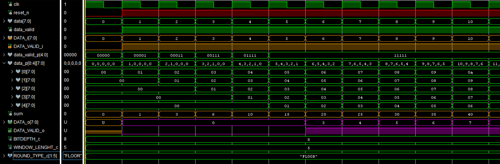 Figure 6 - Outputs of the filter for sequential inputs
The scenario in which the outputs of the filter are examined while DATA_VALID_i = ‘0’ is given in Figure 7.
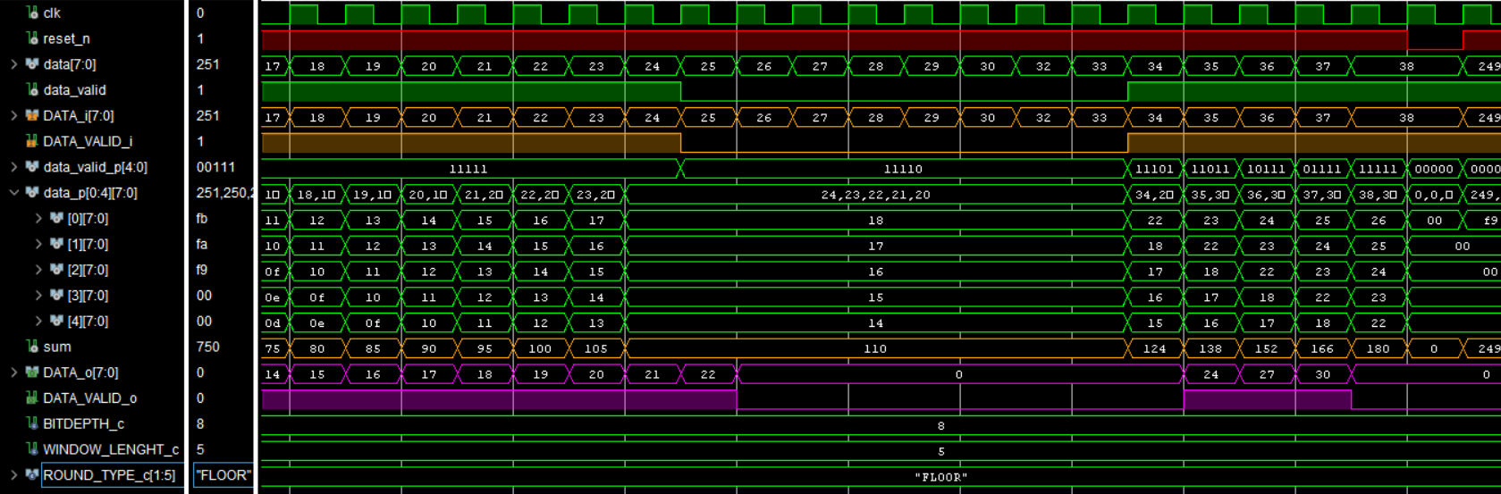 Figure 7 - Outputs of the filter for the inputs while DATA_VALID_i = '0'
The scenario in which the outputs of the filter are examined when DATA_VALID_i returns to ‘1’ after having been ‘0’ is given in Figure 8. Here it can be seen that the old values in the pipeline are preserved.
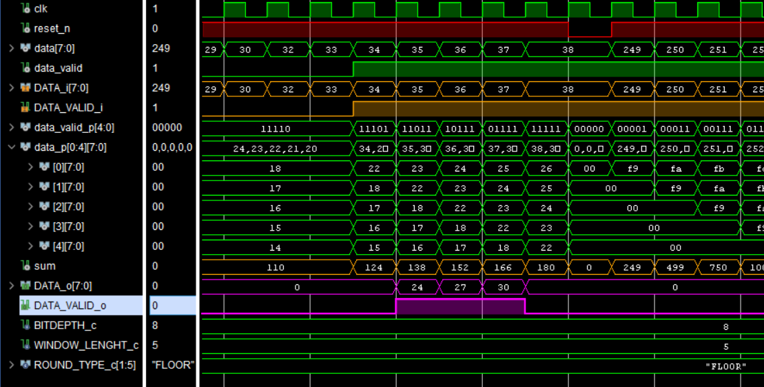 Figure 8 - Outputs of the filter for the inputs when DATA_VALID_i returns to '1' after having been '0'
The scenario in which overflow behaviour is examined by applying input values close to the largest value the input can take is given in Figure 9.
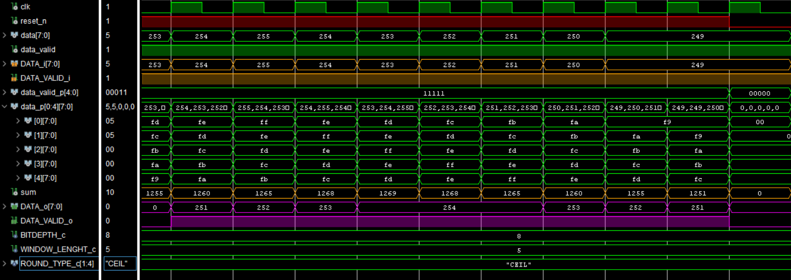 Figure 9 - Examination of the overflow case
The scenario in which the outputs are examined with the ROUND_TYPE_c parameter set to FLOOR and to CEIL is given in Figure 10. Floor rounding is used on the left-hand side of the figure and ceil rounding on the right-hand side.
 Figure 10 - Examination of the effect of the ROUND_TYPE_c parameter on the output
Note: On 21.12.2025 a bug fix was applied to the ceil_log2 function and to the pipeline valid structure in the code.
The following sources were used while preparing this article: Wikipedia - Moving Average, Analog Devices DSP Book and Surf-VHDL - How to Implement Moving Average in VHDL.